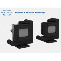
LUNA Spatial Light Modulator
- Stock: Contact us for details
- Click here to: Contact us
- Model: LUNA Spatial Light Modulator
LUNA Spatial Light Modulator
LUNA Spatial Light Modulator
- Reflective LCOS (Phase Only)
- Resolution: 1920 x 1080
- Pixel Pitch: 4.5 µm
- Fill Factor: 91%
- Active Area: 8.64 x 4.86 mm (0.39″ Diagonal)
- Addressing: 8 Bit (256 Phase Levels)
- Signal Formats: DisplayPort – HDTV Resolution
- Input Frame Rate: 60Hz
- Colour Field Rate: 180 Hz – three colour fields
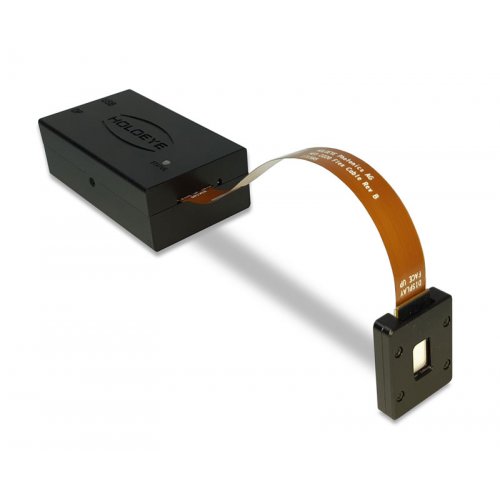
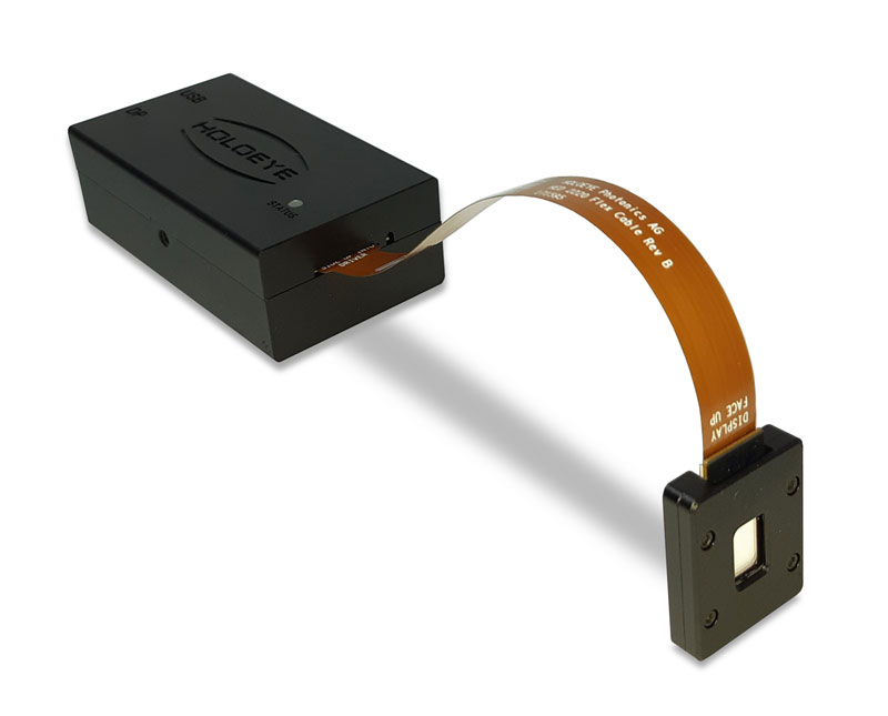
The LUNA Spatial Light Modulator is our most compact SLM platform for integration into small sized or even portable solutions.
The LUNA phase only Spatial Light Modulator (SLM) consists of a driver unit with standard digital video interface (DisplayPort) and a phase only LCOS (Liquid Crystal on Silicon) microdisplay with full HD resolution (1920 x 1080 pixel) and 4.5 µm pixel pitch leading to an active area diagonal of 0.39” with an aspect ratio of 16:9.
The driver ASIC is embedded in the LCOS microdisplay itself. This saves board space which enables a very compact driver and makes integration more convenient. The standard driver box has a size of only 84.4 x 47 x 28.8 mm. The display can even accept video data input via a 4-lane MIPI DSI. This brings phase only Spatial Light Modulator technology to a new level of potential for industrial implementations.
The LUNA SLM uses fast full digital addressing which assures high reliability and a compact driver unit. A certain gray level represents a defined average voltage across the LC cell. This voltage leads to a variable tilt of the LC molecules due to their electrical anisotropy. As LC molecules also show optical anisotropy this tilt changes the refractive index of the LC molecules (for incident polarization along the long display axis) which causes a modified optical path length within the LC cell. The addressed gray level is converted into a phase level.
The LUNA driver unit is equipped with an USB interface for changing the voltage vs. phase level distribution (gamma control) and dynamic range (voltage across the LC cell) in order to calibrate the SLM for different wavelengths.
The LUNA SLM is a plug & play phase modulator and can be addressed with phase functions via standard graphics cards as extended monitor device. Addressing can be done using the supplied Pattern Generator software, the HOLOEYE Slideshow Player software or standard image viewer software. HOLOEYE also provides an SLM Display Software Development Kit (SDK) which provides APIs (Application Programming Interface) for different programming languages.
Model overview

| Version | Wavelength (nm) |
Refl. | Phase Shift (Max.) |
| LUNA-VIS-111 | 420–650 | 61-67 % | 4.3π @ 450 nm 3.2π @ 520 nm 2.4π @ 635 nm |
| LUNA-TELCO-112 | 1400–1700 | 70 % | 2.3π @ 1550 nm |
Please contact us for the latest price.
A number of papers have been published by scientists around the globe who have used a HOLOEYE GAEA series SLM in their research. Here are some examples:
- LCoS SLM Study and Its Application in Wavelength Selective Switch
- Single SLM full-color holographic 3-D display based on sampling and selective frequency-filtering methods
- Holographic image generation with a thin-film resonance caused by chalcogenide phase-change material
- Micro-displays for Holography
A database of published papers, searchable by device or application, can be also found on the HOLOEYE website here.
Elementary Optical Functions
The HOLOEYE Spatial Light Modulator Pattern Generator software was developed for use with all HOLOEYE SLM models. The software allows the simple generation of diverse dynamic optical functions like gratings, lenses, axicons and apertures as well as the calculation of diffractive optical elements (DOE) from user defined images.
Besides the generation of DOEs a wide range of basic optical functions can be created directly via the menu bar. After input of the required parameters the output image appears in a new window. There are several binary and multilevel optical functions possible:
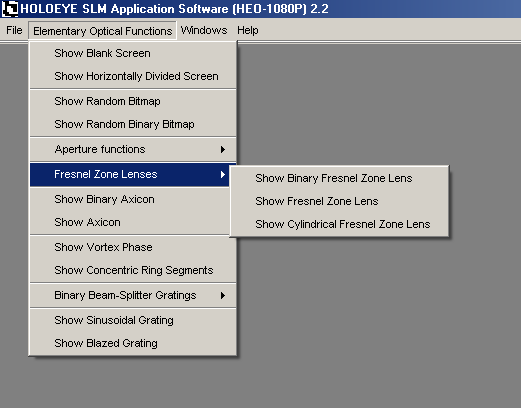
- Blank Grey Level Screen
With this function you can create a homogeneous gray level screen.
- Horizontally Divided Screen
With this function you will create a horizontally divided screen, consisting of two homogeneous graylevel partial screens.
- Random Bitmap
With this function you will create a random pixel distribution using 256 grayscale values. This function can be used to realize the optical function of a random phase plate.
- Aperture Functions
- Rectangular Aperture
- Circular Aperture
-Single Slit and Double Slit
- Fresnel Zone Lenses
-Binary Fresnel Zone Lens
-Multilevel Fresnel Zone Lens
-Cylindrical Fresnel Zone Lens
- Binary Axicon
With this function you will create a Binary Axicon graylevel image representation.
- Axicon
With this function you will create a 256-level Axicon graylevel image representation.
- Vortex Phase
Use this function to create a 256-graylevel image representation of a vortex phase.
- Concentric ring segments
Use this function to create binary images consisting of concentric ring segments.
- Binary beam-splitter gratings
-Linear Gratings and Crossed Linear gratings
-Exemplary binary beam-splitter designs
- Sinusoidal Grating
With this function you will create a sinusoidal grating.
- Blazed Grating
With this function you will create a blazed grating.
- Calculating a beam-shaping phase function for Gaussian Input beams
-Transformation of a Gaussian beam to a circular ‘flat-top’ beam
-Transformation of a Gaussian beam to a rectangular ‘flat-top’ beam
- Superposition with an additional phase map
- e.g. for compensation of aberrations of the optical system or of the SLM


